6. Trees Management - Model, Session and includes#
6.1. Model tree#

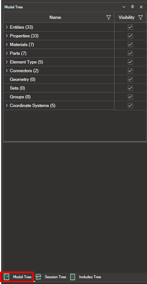
The model tree organizes and structures the finite element model based on various key attributes. Below is an explanation of how to navigate and manage the tree.
The model is divided into the following attributes:
Entities
Properties
Materials
Parts
Element Types
Connectors
Geometry
Sets
Groups
Coordinate Systems
Show/Hide and Options
To expand an attribute and view its content, click the arrow next to the attribute. All attributes can be hidden or shown by checking or unchecking the corresponding box. For example, to hide all entities, check the box next to “Entities”. To hide a specific entity, expand the “Entities” attribute and uncheck the box for that particular entity.

Right-clicking on each attribute reveals the following options:
Isolate
Hide
Copy Name
6.1.2. Attribute Details and Editing Options#
The options and functionalities of each attribute in the content tree are detailed below:
Entities: Entities can be defined according to user settings in Tools -> Options. They can be: NONE, PROPERTIES, PARTS, or ELEMENTTYPE.
Right-clicking on a specific entity reveals the options:
Isolate
Hide
Copy Name
Select Elements/Nodes
In the lower part of the window, the following options are available for editing each entity:
Name
Visible: Allows showing or hiding the entity.
Representation: Allows deciding how the entity will be represented: Opaque_Nowireframe, Opaque_Wireframe, Transparent_Nowireframe, Transparent_Wireframe, etc.
Color: Allows editing the color of the entity.

Properties
Right-clicking on a specific property reveals the options:
Isolate
Hide
Copy Name
Select Elements/Nodes
In the lower part of the window, all information about the selected property is displayed.

Materials
Right-clicking on a specific material reveals the options:
Isolate
Hide
Copy Name
Select Elements/Nodes
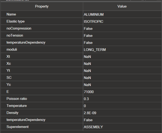
In the lower part of the window, all information about the selected material is displayed.

Parts
Right-clicking on a specific part reveals the options:
Isolate
Hide
Copy Name
Select Elements/Nodes
Element Types
Right-clicking on a specific element type reveals the options:
Isolate
Hide
Copy Name
Select Elements/Nodes
Connectors
Right-clicking on a specific connector reveals the options:
Isolate
Hide
Copy Name
Select Elements/Nodes
Geometry
Right-clicking on a specific geometry reveals the options:
Isolate
Hide
Copy Name
Select Elements/Nodes
Sets: This option is only available for Abaqus models.
Right-clicking on a specific set reveals the options:
Isolate
Hide
Copy Name
Select Elements/Nodes
Groups: As explained in section , when a selection is made and the tool icon is clicked, a new group is created, which will be reflected in this part of the model tree.
Clicking on the group and right-clicking reveals the following options:
Isolate
Hide
Copy Name
Change Group Name
Select Elements/Nodes
Coordinate Systems: This option, in addition to displaying the existing coordinate systems in the model, allows for the creation of new coordinate systems.
Right-clicking on the attribute reveals the following options:
Isolate
Hide
Copy Name
New Coordinate System
6.1.2.1. Create a new coordinate system#
The process for creating a new coordinate system is as follows:
Clicking on New Coordinate System opens a new window.
Enter the new name for the coordinate system.
Select the origin point shape of the coordinate system: Rectangular, Cylindrical, or Spherical.
Select the node in the model that will be the origin point and click the green plus icon to add it.
Specify the First Vector Point (X, Y, or Z) and select the corresponding node from the model.
Specify the Second Vector Point (XY, XZ, YZ).
To add the new coordinate system, click Calculate Coordinates, and it will be displayed in the model tree.
Clicking Clear removes the added data.
Clicking Cancel closes the window and deletes all added information.
Right-clicking on an existing coordinate system in the model reveals the following options:
Isolate
Hide
Copy Name
New Coordinate System
Change Coordinate System Name Right-clicking on a created coordinate system reveals the following options:
Isolate
Hide
Copy Name
New Coordinate System
Delete
Edit
Change Coordinate System Name
6.2.Session tree#

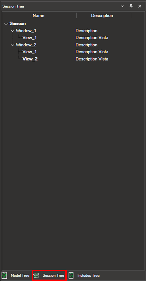
The session tree tool is essential for managing sessions, windows, and views created during your work, as it facilitates the organization and control of different parts of your session, thereby optimizing your workflow.
This tool operates as a content tree. The first level contains the session, the next level contains the windows, and within each window are the views.

Here is a detailed explanation of how to work with this tool and the options available for each level:
6.2.1.Session#
Within the session, you can perform the following actions:
Create windows.
Rename the session.
6.2.2. Window#
Within each session, you can create multiple windows and perform the following actions:
Copy and paste windows.
Create view.
Rename the window.
6.2.3. View#
Within each window, you can create multiple views and perform the following actions:
Expand view: Allows you to expand the view to occupy the entire screen. You can also revert this action to return to the initial position where all views are displayed simultaneously within the window.
Synchronize: Synchronizes the camera movement of the models in all views. This action can be undone to stop synchronizing.
Delete view.
Rename the view.
6.3. Includes Tree#

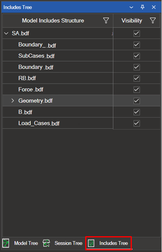
The Includes Tree organizes and structures all the files contained in the input model for Nastran, Abaqus, or Optistruct. Below is a detailed explanation of how to navigate and manage this tree.
6.3.1. Show/Hide and Options#
To expand a file in the input model and view its contents, click the arrow next to the corresponding file. All files can be shown or hidden by checking or unchecking the relevant box.
To hide all files within a main file, uncheck the box next to the main file.
To hide a specific file, expand the main file and uncheck the box for the file you want to hide.
Right-clicking on a file will display the following options:
Isolate
Hide
Select Elements

