
N2PCalculatorRFJoints User Manual#
Overview#
N2PCalculatorRFJoints is a NaxToPy module which provides reserve factor (RF) values for those elements contained inside a N2PGetFasteners object:
Pull-through, bearing and bearing-bypass RFs for composite elements
Pull-through, bearing and net-section RFs for metallic elements.
Tension, shear and combined RFs for 1D elements.
These RFs are obtained using the loads contained inside the corresponding N2PGetLoadFasteners object. To achieve this task, it is necessary to properly define the characteristics of each joint to be analysed. Moreover, it is also possible to use this module without a N2PGetLoadFasteners in order to obtain the following outputs:
A list which links each FEM element to the corresponding N2PJoint object created in N2PGetFasteners.
An echo input file where each allowable value is available for each analysis element.
Example usage 1 #
1. Importing the module#
import NaxToPy as NP
from NaxToPy.Modules.static.fasteners.N2PGetFasteners import N2PGetFasteners
from NaxToPy.Modules.static.fasteners.N2PGetLoadFasteners import N2PGetLoadFasteners
from NaxToPy.Modules.static.fasteners.joints.N2PFastenerSystem import N2PFastenerSystem
from NaxToPy.Modules.static.fasteners.N2PCalculatorRFJoints import N2PCalculatorRFJoints
2. Load the model#
model = NP.load_model(r"file path")
3. Create and calculate N2PGetFasteners object#
fasteners = N2PGetFasteners()
fasteners.Model = model
fasteners.GetAttachmentsBool = True
fasteners.GetDistanceBool = True
fasteners.calculate()
4. Create N2PCalculatorRFJoints object#
rf = N2PCalculatorRFJoints()
rf.GetFasteners = fasteners
rf.ExportLocation = r"path"
rf.elements_manager_filter(mode = "SIMPLE", table_print = "EXCEL")
rf.calculate()
Example usage 2 #
1. Importing the module#
import NaxToPy as NP
from NaxToPy.Modules.static.fasteners.N2PGetFasteners import N2PGetFasteners
from NaxToPy.Modules.static.fasteners.N2PGetLoadFasteners import N2PGetLoadFasteners
from NaxToPy.Modules.static.fasteners.joints.N2PFastenerSystem import N2PFastenerSystem
from NaxToPy.Modules.static.fasteners.N2PCalculatorRFJoints import N2PCalculatorRFJoints
2. Load the model#
model = NP.load_model(r"file path")
3. Create and calculate N2PGetFasteners object#
fasteners = N2PGetFasteners()
fasteners.Model = model
fasteners.GetAttachmentsBool = True
fasteners.GetDistanceBool = True
fasteners.calculate()
4. Create and calculate N2PGetLoadFasteners object#
loads = N2PGetLoadFasteners()
loads.GetFasteners = fasteners
loads.AnalysisName = "LH_Leading_Edge_Rivets"
loads.ResultsFiles = [r"results_1.op2", r"results_2.op2", r"results_3.op2"]
loads.OptionalAttributes.DefaultDiameter = 4.0
loads.calculate()
5. Assignate N2PFastenerSystem to each N2PJoint#
# FastenerSystem definition
Fastener_HWGT314 = N2PFastenerSystem()
Fastener_HWGT314.Designation = "HWGT314-4-LEADING-EDGE"
Fastener_HWGT314.Fastener_pin_single_SH_allow = 4444.0
Fastener_HWGT314.Fastener_collar_single_SH_allow = 4444.0
Fastener_HWGT314.Fastener_pin_tensile_allow = 4444.0
Fastener_HWGT314.Fastener_collar_tensile_allow = 4444.0
Fastener_HWGT314.D_head = 10.4
Fastener_HWGT314.D_tail = 9.4
Fastener_HWGT314.D_nom = 4.0

# FastenerSystem assignation
for joint in fasteners.JointsList:
    joint.FastenerSystem = Fastener_HWGT314
Warning
CRITICAL: The methods described later for each failure mode do not consider any b-value/mean value/a-value KDF. In those cases where the user wants to include a b-value/mean value/a-value KDF, this must be incorporated when setting the allowable value. All failure modes described within this documentation assume \(C_{BV}=1.00\).
6. N2PCalculatorRFJoints calculate()#
# N2PCalculatorRFJoints definition:
rf = N2PCalculatorRFJoints()
rf.GetFasteners = fasteners
rf.ExportLocation = r"path"
rf.elements_manager_filter(mode = "ADVANCED", table_print = "EXCEL")
7. Allowables definition#
# Materials Allowables Definition -> Inter Laminate Shear Stress
for key in rf.AnalysisCompMats:
    rf.AnalysisCompMats[key]._allowableORTO.ILSS = 200.00

# Laminates Allowables Definition:
for key in rf.AnalysisCompProps:
    rf.AnalysisCompProps[key].BearingAllowable = 400.0     # Bearing
    rf.AnalysisCompProps[key].OHTAllowable = 7222.0E-6     # Open hole tension
    rf.AnalysisCompProps[key].OHCAllowable = -3632.0E-6    # Open hole compression
    rf.AnalysisCompProps[key].FHTAllowable = 7222.0E-6     # Filled hole tension
    rf.AnalysisCompProps[key].FHCAllowable = -3632.0E-6    # Filled hole compression

# Metallic Properties Allowables Definition:
for key in rf.AnalysisMetalProps:
    rf.AnalysisMetalProps[key].Fbru_e1p5d = 600.0   #Bearing ultimate allowable ed_1.5
    rf.AnalysisMetalProps[key].Fbru_e2d = 650.0     #Bearing ultimate allowable ed_2.0
    rf.AnalysisMetalProps[key].Ftu = 500.0          #Ultimate tensile strength
Warning
CRITICAL: The methods described later for each failure mode do not consider any b-value/mean value/a-value KDF. In those cases where the user wants to include a b-value/mean value/a-value KDF, this must be incorporated when setting the allowable value. All failure modes described within this documentation assume \(C_{BV}=1.00\).
Note
OHCAllowable and FHCAllowable can be written as positive or negative values, it does not affect the results obtention.
8. GetLoadFasteners definition and RF calculation#
# N2PGetLoadFasteners object is introduced into the module
rf.GetLoadFasteners = loads

# Rfs are calculated
rf.calculate()
9. Ouputs printing#
# Minimum RFs values are printed into a CSV file
rf.rf_min_and_lc_to_CSV()

# Minimum RFs values are printed into an EXCEL file
rf.rf_min_and_lc_to_EXCEL()

# All RFs values are printed into a CSV file
rf.rf_and_lc_to_CSV()
Setup#
Mandatory Prerequisites#
Python Environment: Ensure you have a compatible Python environment with the following libraries:
NaxToPy modules
NaxToPy Framework: The module integrates with the NaxToPy library, which must be installed and configured in your environment.
Optional Prerequisites#
Python Environment:
Pandas: only required if the user asks for Excel output while setting table_print = “EXCEL” in “elements_manager_filter” method or while calling “rf_min_and_lc_to_EXCEL” method.
Module Inputs#
The class N2PCalculatorRFJoints provides three different kind of information about each FEM element contained inside a N2PGetFasteners object:
Applied loads
Element allowables values
Reserve Factors (RF)
This class has been designed so as to be run it two times:
First run (see Example usage 1) -> this enables the user to check the corresponding Joint Id associated to each FEM element. This step is vital in order to assign allowable values to each N2PJoint. Without this values assignation, this class cannot offer any RF.
Second run (see Example usage 2) -> when all the joints have the required data, the reserve factors can be calculated.
Mandatory Inputs#
Property |
Type |
Description |
|---|---|---|
(for each N2PJoint object) -> .FastenerSystem |
|
N2PFastenerSystem object assigned to each N2PJoint |
.GetFasteners |
|
N2PGetFasteners object with the joints to be studied |
.AnalysisCompMats[key]._allowableORTO.ILSS |
|
Interlaminate shear strength for each analised composite material |
.AnalysisCompProps[key].BearingAllowable |
|
Bearing allowable stress [strength] for each analised composite property |
.AnalysisCompProps[key].OHTAllowable |
|
Open Hole Tension Strains allowable [strength] for each analised composite property |
.AnalysisCompProps[key].OHCAllowable |
|
Open Hole Compression Strains allowable [strength] for each analised composite property |
.AnalysisCompProps[key].FHTAllowable |
|
Filled Hole Tension Strains allowable [strength] for each analised composite property |
.AnalysisCompProps[key].FHCAllowable |
|
Filled Hole Compression Strains allowable [strength] for each analised composite property |
.AnalysisMetalProps[key].Fbru_e1p5d |
|
Ultimate Bearing allowable [strength] of the shell for e/D = 1.5 for each analysed metallic property |
.AnalysisMetalProps[key].Fbru_e2d |
|
Ultimate Bearing allowable [strength] of the shell for e/D = 2 for each analysed metallic property |
.AnalysisMetalProps[key].Ftu |
|
Ultimate Tension allowable [strength] of the shell for each analysed metallic property |
.GetLoadFasteners |
|
N2PGetLoadFasteners object with the loads to be used |
Warning
CRITICAL: The methods described later for each failure mode do not consider any b-value/mean value/a-value KDF. In those cases where the user wants to include a b-value/mean value/a-value KDF, this must be incorporated when setting the allowable value. All failure modes described within this documentation assume \(C_{BV}=1.00\).
Optional Inputs#
Property |
Type |
Description |
|---|---|---|
.ExportLocation |
|
Path to the directory where output files will be stored |
# Provided that .ExportLocation is defined, several outputs can be exported (See Example of Usage #2)
(...)

rf.elements_manager_filter(mode = "ADVANCED", table_print = "EXCEL")

(...)

rf.rf_min_and_lc_to_CSV()

rf.rf_min_and_lc_to_EXCEL()

rf.rf_and_lc_to_CSV()

(...)
Conditional Inputs#
In some cases, the user may not know the value of the ILLS of each material of a given PCOMP property. In this case, the user must define the laminate PT allowable using the following property. In those cases where both data (ILLS and PTAllowable) are given, the most restrictive value will be automatically chosen to calculate the pull-through reserve factor value.
Property |
Type |
Description |
|---|---|---|
.AnalysisCompProps[key].PTAllowable |
|
Pull Through strength allowable [strength] for each analised composite property |
Warning
CRITICAL: The methods described later for each failure mode do not consider any b-value/mean value/a-value KDF. In those cases where the user wants to include a b-value/mean value/a-value KDF, this must be incorporated when setting the allowable value. All failure modes described within this documentation assume \(C_{BV}=1.00\).
FEM Requirements#
For this module to function properly, the FEM model must include forces in the output requests. Additionally, the model should accurately represent all elements and load cases used in the analysis, including fasteners, elements pierced by fasteners, and elements surrounding them. This module is avaible for Nastran and Optistruct and only FEM elements with properties “PSHELL”, “PCOMP”, “PFAST” and “CWELD” elements are supported.
Supported Type Files#
Solver |
File Extension |
|---|---|
Nastran |
.op2 |
Nastran |
.xdb |
Nastran |
.h5 |
Optistruct |
.op2 |
Optistruct |
.h3d |
N2PFastenerSystem creation#
A N2PFastenerSystem object is a part of a N2PJoint object that represents a specific fastener designation whose values need to be defined by the user in order to obtain RF values for one or more failure modes. Its attributes must be added as properties See Table 1:
Designation(str): fastener system name (No Default)Fastener_pin_single_SH_allow(float/int): fastener pin single shear strength allowable [force] (No Default)Fastener_collar_single_SH_allow(float/int): fastener collar single shear strength allowable [force] (No Default)Fastener_pin_tensile_allow(float/int): fastener pin tensile strength allowable [force] (No Default)Fastener_collar_tensile_allow(float/int): fastener collar tensile strength allowable [force] (No Default).D_head(float/int): head diameter (No Default)D_tail(float/int): tail diameter (No Default)D_nom(float/int): nominal diameter (No Default)Configuration(str): “BOLT” or “RIVET” or “SOLID” (Default: “BOLT”)FastenerType(str): “LOCK” or “BLIND” (Default: “LOCK”)FastenerInstallation(str): “PERMANENT” or “REMOVABLE” or “QUICK RELEASE” (Default: “PERMANENT”)FastenerHead(str): “PAN” or “CSK” (Default: “PAN”)FloatingNut(bool): True or False (bool) (Default: False)AluminumNut(bool): True or False (bool) (Default: False)
Warning
CRITICAL: The methods described later for each failure mode do not consider any b-value/mean value/a-value KDF. In those cases where the user wants to include a b-value KDF, this must be incorporated when setting the allowable value. All failure modes described within this documentation assume \(C_{BV}=1.00\)
Tip
If collar allowable values are unknow, please write the same values that are being used for pin side. By doing so, the user is just assuming that the shear/tensile allowable strength of the collar region is the same as the rest of the pin. On the contrary, if this value is known, it is recommended to use it for improved accuracy of the results.
Table 1: N2PFastenerSystem properties
Property |
Category |
Data Type |
Applicable value |
|---|---|---|---|
Designation |
Mandatory |
str |
30 characters (Maximum) |
Fastener_pin_single_SH_allow |
Mandatory |
float/int |
> 0 |
Fastener_collar_single_SH_allow |
Mandatory |
float/int |
> 0 |
Fastener_pin_tensile_allow |
Mandatory |
float/int |
> 0 |
Fastener_collar_tensile_allow |
Mandatory |
float/int |
> 0 |
D_head |
Mandatory |
float/int |
> 0 |
D_tail |
Mandatory |
float/int |
> 0 |
D_nom |
Mandatory |
float/int |
> 0 |
Configuration |
Optional |
str |
“BOLT”, “RIVET”, “SOLID” |
FastenerType |
Optional |
str |
“LOCK”, “BLIND” |
FastenerInstallation |
Optional |
str |
“PERMANENT”, “REMOVABLE”, “QUICK RELEASE” |
FastenerHead |
Optional |
str |
“PAN”, “CSK” |
FloatingNut |
Optional |
bool |
True, False |
AluminumNut |
Optional |
bool |
True, False |
# ((EXAMPLE)) -> Complete FastenerSystem definition

Fastener_HWGT314 = N2PFastenerSystem()
Fastener_HWGT314.Designation="HWGT314-4-LEADING-EDGE"
Fastener_HWGT314.Fastener_pin_single_SH_allow=4444.0
Fastener_HWGT314.Fastener_collar_single_SH_allow=5555.0
Fastener_HWGT314.Fastener_pin_tensile_allow=6666.0
Fastener_HWGT314.Fastener_collar_tensile_allow=7777.0
Fastener_HWGT314.D_head=10.4
Fastener_HWGT314.D_tail=9.4
Fastener_HWGT314.D_nom=4.0
Fastener_HWGT314.Configuration = "RIVET"
Fastener_HWGT314.FastenerType = "LOCK"
Fastener_HWGT314.FastenerInstallation = "PERMANENT"
Fastener_HWGT314.FastenerHead = "PAN"
Fastener_HWGT314.FloatingNut = True
Fastener_HWGT314.AluminumNut = True
N2PJointAnalysisParameters creation#
A N2PJointAnalysisParameters object is a part of a N2PJoint object that represents a specific INPUT parameters to obtain the joint RF values (for compositemetal plates and bolt). In contrast with the N2PFastenerSystem, this object is not necessarilly an user input, but the user can change any of its values before RFs calculation.
All the properties of this class are automatically calculated using both model and FastenerSystem information. If the user wants to change the default values obtained, such properties must be be individually modified before the RF calculation.
ShearType(str): defines the support condition for each N2PJoint depending on the surrounding structure and the joint configuration. (str = “DLS” or “SLS-S” or “SLS-U”) (Default: “SLS-U”)CenvMet(float): enviromental KDF for met parts. For all failure modes in the same way. (Default: 1.00)CenvComp(type): enviromental KDF for comp parts. For all failure modes in the same way. (Default: 1.00)UserKDFComp(float): user defined KDF which applies to all comp failure modes at RF level. Intended to account for Fitting Factor, Buttjoint, Safety Factor. (Default: 1.00)UserKDFMet(float): user defined KDF which applies to all met failure modes at RF level. Intended to account for Fitting Factor, Buttjoint, Safety Factor. (Default: 1.00)UserKDFBoltShear(float): user defined KDF for bolt shear failure mode at RF level. Intended to account for several bolt factors. (Default: 1.00)UserKDFBoltTension(float): user defined KDF for bolt tension failure mode at RF level. Intended to account for several bolt factors. (Default: 1.00)M(float): slope of the composite bearing-bypass interaction curve (value between [3, 4]) (Default: 4.0)TShim(float): total shim thickness applied to the joint expressed in mm. Includes solid and liquid shim. (Default: 0.0)TShimL(float): liquid shim thickness applied to the joint expressed in mm. Includes solid and liquid shim. (Default: 0.0)
Warning
TShim and TShimL must be expressed in milimeters
CPrying(float): aplied to the tension loads of the failure modes of the external plates. (Default: 1.0)
Fig. 1 Recommended expression for \(C_{Prying}\) calculation for L-profile joints.#

Fig. 2 Recommended expression for \(C_{Prying}\) calculation for T-profile joints.#
PT_Alpha_Met(float): coeficient alpha of the pull-througth allowable curve for metallic plates, applicable to head side (and tail side, optionally) (Default: 150.0)PT_Gamma_Met(float): coeficient gamma of the pull-througth allowable curve for metallic plates, applicable to head side (and tail side, optionally) (Default: 270.0)EdgeDistance(list[float]): list which contains the edge distance parameter of each plate of the joint. One value for each plate of the joint. (Default: automatically calculated from N2PPlate data). This parameter is not always the “edge distance” value obtained directly through the mesh as it is indicated below.EffectiveWidth(list[float]): list which contains the plate effective width of each plate of the joint. One value for each plate of the joint. (Default: automatically calculated from N2PPlate and N2PJoint data).
Fig. 3 Effective Width and Edge Distance Parameters calculation for Composite plates.#

Fig. 4 Effective Width and Edge Distance Parameters calculation for Metallic plates.#
NetRatio(list[float]): list which contains the plate net ratio of each plate of the joint. One value for each plate of the joint. (Default: automatically calculated from N2PPlate and N2PJoint data).
NetSectionArea(list[float]): list which contains the net section area for the net section metallic failure mode of each plate of the joint. One value for each plate of the joint. (Default: automatically calculated from N2PPlate and N2PJoint data).
Coef_A_CombinedMet(list[float]): list which contains the coefficient “a” for combined interaction allowable curve for every plate of the joint. For those plates being made out of composite material, “None” value will be printed. See Table 2Coef_B_CombinedMet(list[float]): list which contains the coefficient “b” for combined interaction allowable curve for every plate of the joint. For those plates being made out of composite material, “None” value will be printed. See Table 2Coef_Alpha_CombinedComp(list[float]): list which contains the coefficient alpha for combined interaction allowable curve for every plate of the joint. For those plates being made out of metallic material, “None” value will be printed. See Table 3Coef_Beta_CombinedComp(list[float]): list which contains the coefficient beta for combined interaction allowable curve for every plate of the joint. For those plates being made out of metallic material, “None” value will be printed. See Table 3Coef_SRF_NetSection_Met(list[float]): list which contains the stress reduction factor \(C_{SRF-NS}\) for every plate of the joint for net section failure of metallic plates. For those plates being made out of composite material, “None” value will be printed.
Table 2: Combined interaction coefficients for metallic plates
Configuration |
Installation |
Type |
Aluminum Nut |
Head |
a Coefficient |
b Coefficient |
|---|---|---|---|---|---|---|
BOLT |
PERMANENT |
LOCK |
FALSE |
- |
2.0 |
3.0 |
BOLT |
PERMANENT |
LOCK |
TRUE |
- |
1.0 |
12.0 |
BOLT |
PERMANENT |
BLIND |
- |
- |
2.5 |
1.3 |
BOLT |
QUICK RELEASE |
- |
- |
CSK |
1.3 |
min([0.8+(t/d), 1.3]) |
BOLT |
QUICK RELEASE |
- |
- |
PAN |
2.0 |
3.0 |
BOLT |
REMOVABLE |
- |
- |
- |
1.3 |
min([0.8+(t/d), 1.3]) |
RIVET |
- |
BLIND |
FALSE |
- |
2.5 |
1.3 |
RIVET |
- |
- |
- |
- |
2.0 |
3.0 |
SOLID |
- |
- |
- |
PAN |
2.0 |
2.0 |
SOLID |
- |
- |
- |
CSK |
2.0 |
3.0 |
Table 3: Combined interaction coefficients for composite plates
Side |
Configuration |
Type |
Head |
Floating Nut |
α Coefficient |
β Coefficient |
|---|---|---|---|---|---|---|
Head |
BOLT |
LOCK |
PAN |
- |
2.0 |
2.0 |
Head |
BOLT |
LOCK |
CSK |
- |
1.8 |
min([0.8 + (t/d), 1.8]) |
Head |
BOLT |
BLIND |
- |
- |
1.8 |
min([0.8 + (t/d), 1.3]) |
Head |
RIVET |
- |
- |
- |
1.3 |
min([0.8 + (t/d), 1.3]) |
Head |
SOLID |
- |
- |
- |
1.8 |
1.8 |
Tail |
BOLT |
LOCK |
- |
- |
2.0 |
2.0 |
Tail |
BOLT |
BLIND |
- |
- |
1.8 |
min([0.8 + (t/d), 1.3]) |
Tail |
RIVET |
- |
- |
- |
1.3 |
min([0.8 + (t/d), 1.3]) |
Tail |
- |
- |
- |
True |
1.3 |
min([0.8 + (t/d), 1.3]) |
Middle* |
- |
- |
- |
- |
1.8 |
1.8 |
(*): This is a default assignation, middle plates are not relevant for bolt-combined failure mode.
Output Description#
Please refer to Example of Usage 2 to see how to ask for outputs when running this class.
Common Errors#
E900: fastenerSystem is found while trying to create and N2PJointAnalysisParameters object.E901: the user does not introduce a valid parameter when running the elements_manager_filter method() at N2PCalculatorRFJoints.E902: the user does not introduce the appropiate data type to a N2PJointAnalysisParameter property.E903: the user does not introduce the appropiate data size to a N2PJointAnalysisParameter property.E904: N2PCompRF finds a not valid TShim for the INDUSTRIAL method. Tshim=2.5 is set.E905: N2PCalculatorRFJoints does not find Pandas to write the requested element filter print excel file. Analysis elements are printed in CSV format as EXCEL option cannot be used.E906: N2PCalculatorRFJoints does not find Pandas to write the requested RF excel file.E907: net-section allowable calculation has failed in N2PMetalRF class because Anet/Agross is negative.E908: SEE LOG FILE: For one or more elements, Error E900 has been raised.E909: SEE LOG FILE: For one or more elements, Error E904 has been raisedE910: SEE LOG FILE: For one or more elements, Error E907 has been raised
Common Warnings#
W900: raised when no GetLoadFastener object is found while calling method calculate() at N2PCalculatorRFJoints.W901: when running N2PCompRF, the edge distance of an 2D element is not within method limits. SEE METHOD DOCUMENTATION (COMP ; BEARING; KDF EDGE DISTANCE EFFECT): e/d cannot be lower than 1.80W902: 2D element’s property is neither PSHELL nor PCOMP. This element will be ignored for the analysis.W903: 2D element’s e/d is lower than 1.5 in N2PMetalRF. If (e/d) ratio is lower than 1.5, then it is assumed that \(f_{bru}= min \left( f_{bru}(e/d = 1.5) ; f_{bru}(e/d = 2.0)\right )\)W904: C_SRF_NS cannot be calculated and it is assumed to be 1.0 in N2PJointAnalysisParameters as (D/W) is greater than 0.5.W905: SEE LOG FILE: For one or more elements, Warning W902 has been raised.W906: SEE LOG FILE: For one or more elements, Warning W905 has been raised.W907: SEE LOG FILE: For one or more elements, Warning W901 has been raised.W908: SEE LOG FILE: For one or more elements, Warning W903 has been raised.
Common Critical Errors#
C900: the user has not introduced the appropiate data to a N2PFastenerSystem property.C901: the user does not introduce the appropiate data to a N2PCalculatorRFJoints property.C902: the user has not introduced a N2PGetFasteners object before calling the elements_manager_filter() method in N2PCalculatorRFJoints class.C903: a specific N2PFastenerSystem parameter is missing for RF calculation.C904: the user has asked for outputs but does not define the ExportLocation property at N2PCalculatorRFJoints.C905: a metallic material parameter is not defined and class N2PMetalRF fails.C906: PTAllowable cannot be obtained in N2PCompRF class due to an user input missing parameter.C907: a composite laminate property parameter is not defined and class N2PCompRF fails.C908: RF output cannot be created if N2PGetLoadFasteners has not been provided.
Methodology#
Please refer to each axiliary class to see the applicable methodology apply inside this module:
N2PCompRF to see how composite elements are studied.
N2PMetalRF to see how metallic elements are studied.
N2PRivetRF to see how 1D elements are studied.
Auxiliary classes#
N2PCompRF #
This class calculates RFs for every composite element contained inside each N2PJoint contained inside the N2PGetFasteners input using the available loads introduced through the N2PGetLoadFasteners object. This class only accepts elements whose property is a PCOMP.
Pull-Through Reserve Factor (Industrial Method)#
Pull-through failure occurs when a fastener (e.g., a bolt, rivet, or screw) pulls through the material it is fastened to, rather than failing due to shear or tensile forces on the fastener itself. This failure takes place when the material around the connector hole fails, allowing the fastener to “pull through” the material. The reserve factor associated to this failure mode is calculated using the following expression:
Where the meaning of each element is described as follows:
\(F_{\text{PT-allow}}\): the allowable pull-through load (force) for a specific 2D element
\(UserKDF\): property of the object N2PJointAnalysisParameter (UserKDFComp)
\(C_{\text{prying}}\): property of the object N2PJointAnalysisParameter (CPrying)
\(P\): tension load of the connector for a given load case. For those load cases in which P<0, this RF is printed as 9999.00 at the output as this failure mode cannot take place
Furthermore, the value of \(F_{\text{PT-allow}}\) is obtained through the following expression:
Where the meaning of each element is described as follows:
\(F_{\text{PT}}\): allowable pull-through strength at room temperature at dry conditions
\(D\): bolt or nut head/tail diameter
\(t\): thickness of the 2D element evaluated
\(C_{\text{BV}}\): b-value knock-down factor for pull-through failure
\(C_{\text{ENV}}\): environmental effects (ageing, temperature) knock-down factor for pull-through failure
\(C_{\text{BT}}\): bolt type knock-down factor
\(ksc\): stress concentration factor due to asymmetrical loading
\(F_T\): allowable tensile connector bolt load
Table 4: Pull-through allowables parameters for composite elements
Parameter |
Description |
User Depending ? |
Input Type |
|---|---|---|---|
\(F_{\text{PT}}\) |
Laminate* pull-through allowable |
Yes |
Conditional -> See Note #1 |
\(D\) |
Head or tail diameter |
Yes |
Mandatory -> N2PFastenerSystem D_head and D_tail |
\(t\) |
Laminate thickness |
No |
- |
\(C_{\text{BV}}\) |
B-value KDF -> always 1.00 |
No |
- |
\(C_{\text{ENV}}\) |
Environment KDF |
Yes |
Conditional -> N2PJointAnalysisParameters CenvComp (Default: 1.00) |
\(C_{\text{BT}}\) |
Bolt type KDF -> 0.90 for CSK and 1.00 for PAN |
Yes |
Conditional -> N2PFastenerSystem FastenerHead (Default: “PAN”) |
\(ksc\) |
Stress concentration factor due to asymmetrical loading |
No |
- |
\(F_T\) |
Collar or pin allowable tensile load |
Yes |
Mandatory -> N2PFastenerSystem Fastener_pin_tensile_allow and Fastener_collar_tensile_allow |
(*): Laminate represents CompositeShell object whose allowables have to be defined after using the method elements_manager_filter and before the method calculate() of this class.
Note #1: If Laminate.PTAllowable is not provided by the user, then this class will take the minimum ILLS value for each material of the laminate.
Note #2: for those load cases where the connector is experiencing compression loads, RF will be printed as 9999.00.
Bearing Reserve Factor (Industrial Method)#
Bearing failure occurs when a fastener applies compressive loads to a plate and the material located around the hole experiences high stress concentrations. The reserve factor associated to this failure mode is calculated using the following expression:
Where the meaning of each element is described as follows:
\(F_{\text{BEA-allow}}\): calculated bearing strength allowable. It depends on several parameters, as it is explained later.
\(\sigma_{\text{bea}}\): bearing stress applied on the hole. By convention, \(\sigma_{\text{bea}} \geq 0\)
\(UserKDF\): property of the object N2PJointAnalysisParameter (UserKDFComp)
Furthermore, the value of \(f_{\text{BEA-allow}}\) is obtained through the following expression:
Where the meaning of each element is described as follows:
\(F_{base}\): reference bearing strength stress of the laminate
\(C_{JT}\): joint type knock-down factor
\(C_{e/d}\): edge distance knock-down factor
\(C_{ENV}\): environmental effects (ageing, temperature) knock-down factor
\(C_{torq}\): torque factor knock-down factor
\(C_{shim}\): shimming influence knock-down factor
\(C_{mod}\): modulus variation factor knock-down factor
\(C_{BV}\): b-value knock-down factor
Table 5: Bearing allowables parameters
Parameter |
Description |
User Depending ? |
Input Type |
|---|---|---|---|
\(f_{base}\) |
Laminate bearing allowable stress |
Yes |
Mandatory -> CompositeShell BearingAllowable |
\(C_{JT}\) |
Joint type KDF -> 1.00 for DLS, 0.75 for SLS-U and SLS-S |
Yes |
Conditional -> N2PJointAnalysisParameters ShearType (Default: “SLS-U”) |
\(C_{e/d}\) |
Edge distance KDF (see note #1) |
Yes |
Conditional -> N2PJointAnalysisParameters EdgeDistance (Default: automatically obtained) |
\(C_{ENV}\) |
Environment KDF |
Yes |
Conditional -> N2PJointAnalysisParameters CenvComp (Default: 1.00) |
\(C_{torq}\) |
Torque factor KDF -> always 1.00 |
No |
- |
\(C_{shim}\) |
Shimming influence KDF (see note #2) |
Yes |
Conditional -> N2PJointAnalysisParameters TShim (Default: 0.0) |
\(C_{mod}\) |
Modulus variation KDF (see note #3) |
No |
- |
\(C_{BV}\) |
B-value KDF -> always 1.00 |
No |
- |
(*): Laminate represents CompositeShell object whose allowables have to be defined after using the method elements_manager_filter and before the method calculate() of this class. See example usage 2.
Note #1: the edge distance knock-down factor is calculated using the edge distance obtained from N2PGetFasteners \(\left( e \right)\) and the nominal diameter of the connector \(\left( d \right)\) using the following expression:
Please note that if \(1.8 > \frac{e}{d}\) for an element, Warning W901 is raised in the log file and it is assumed that \(C_{e/d}=\frac{e}{3d}\) in order to avoid the calculation process interruption.
Note #2: the shimming influence knock-down factor is calculated using the joint ShearType, the element thickness \(\left( e \right)\) and the shim thickness \(\left( t_{shim} \right)\). It assumes that \( t_{shim} \) must be equal or lower than 2.5 mm and it is calculated as follows:
Please note that if \( t_{shim} > 2.5\), Error E904 is raised in the log file.
Note #3: the modulus variation knock-down factor is obtained performing through a comparison between the analysis laminate and its corresponding quasi-isotropic laminate. Once this new laminate has been defined, a comparison between their elastic modulus takes place in order to provide a value of this KDF:
Bearing-ByPass Reserve Factor (Industrial Method)#
This failure mode is to be studied to considerer the simultaneous effects of bearing loads and loads that bypass a composite hole. The ratio between bearing load and bypass load depends on the joint stiffness and its particular configuration. Depending on the value of this load ratio, one or another failure mode will take place at each hole.

Fig. 5 Visual representation of the bearing-bypass reserve factor obtention.#
The following expression provides a RF for bearing-bypass failure mode:
Where the meaning of each element is described as follows:
\(UserKDF\): property of the object N2PJointAnalysisParameter (UserKDFComp)
\(S_{\text{bea-allow}}\): bearing allowable stress
\(S_{\text{by-allow}}\): by-pass allowable stress
\(\sigma_{\text{bea}}\): applied bearing stress
\(\sigma_{\text{by}}\): applied by-pass stress
Its is important to remark that the stresses set \(\left( \sigma_{\text{bea}},\text{ } \sigma_{\text{by}} \right)\) determines the bearing/by-pass ratio called \(\beta\), which is reponsible to determine the set of allowables values \(\left( S_{\text{bea-allow}}, \text{} S_{\text{by-allow}} \right)\). Furthermore, the origin of each allowable value should be properly explained:
\(S_{\text{bea-allow}}\): calculated as per bearing failure chapter.
\(S_{\text{by-allow}}\): calculated using \(\beta\) and the net-section allowable value \(S_{\text{by-all}}^{\text{Net-section}}\) which comes from the following expression:
Table 6: Net section allowable parameters
Parameter |
Description |
User Depending ? |
Input Type |
|---|---|---|---|
\(OHC\) |
Laminate open hole compression strength strains |
Yes |
Mandatory -> CompositeShell OHCAllowable |
\(FHC\) |
Laminate filled hole compression strength strains |
Yes |
Mandatory -> CompositeShell FHCAllowable |
\(OHT\) |
Laminate open hole tension strength strains |
Yes |
Mandatory -> CompositeShell OHTAllowable |
\(FHT\) |
Laminate filled hole compression strength strains |
Yes |
Mandatory -> CompositeShell FHTAllowable |
\(E_{1}\) |
Equivalent laminate membrane Ex modulus (assumption) |
No |
- |
\(E_{2}\) |
Equivalent laminate membrane Ey modulus (assumption) |
No |
- |
\(C_{ENV}\) |
Environment KDF |
Yes |
Conditional -> N2PJointAnalysisParameters CenvComp (Default: 1.00) |
\(\beta\) |
Slope of the composite bearing-bypass interaction curve |
Yes |
Conditional -> N2PJointAnalysisParameters M (Default: 4.00) |
(*): Laminate represents CompositeShell object whose allowables have to be defined after using the method elements_manager_filter and before the method calculate() of this class. See example usage 2.
In terms of the applied stresses, the applied bearing stress \(\sigma_{\text{bea}}\) is calculated as it has been previously introduced in \(RF_{bearing}\) formulation, while the applied by-pass stress requires the use of the Mohr’s circle:
where \(N_{\text{x}}\), \(N_{\text{y}}\) and \(N_{\text{xy}}\) represent the bypass fluxes of the composite plate for a given load case and they are expressed in [N/mm].
N2PMetalRF #
This class calculates RFs for every metallic element contained inside each N2PJoint contained inside the N2PGetFasteners input using the available loads introduced through the N2PGetLoadFasteners object. This class only accepts elements whose property is a PSHELL.
Pull-Through Reserve Factor (Industrial Method)#
Pull-through failure occurs when a fastener (e.g., a bolt, rivet, or screw) pulls through the material it is fastened to, rather than failing due to shear or tensile forces on the fastener itself. This failure takes place when the material around the connector hole fails, allowing the fastener to “pull through” the material. The reserve factor associated to this failure mode is calculated using the following expression:
Where the meaning of each element is described as follows:
\(F_{\text{PT-allow}}\): the allowable pull-through load (force) for a specific 2D element
\(UserKDF\): property of the object N2PJointAnalysisParameter (UserKDFMet)
\(C_{\text{prying}}\): property of the object N2PJointAnalysisParameter (CPrying)
\(P\): tension load of the connector for a given load case. For those load cases in which P<0, this RF is printed as 9999.00 at the output as this failure mode cannot take place
Furthermore, the value of \(F_{\text{PT-allow}}\) is obtained through the following expression:
Where the meaning of each element is described as follows:
\(D\): nominal diamater of the connector
\(\alpha\), \(\gamma\): empirical coefficients for pull through allowable curves
\(t\): element thickness
\(F_{T}\): fastener allowable tension [force]
\(C_{SRF-PT}\): pull-through stress reduction factor for metallic elements
\(C_{ENV}\): environmental effects (ageing, temperature) knock-down factor
\(C_{BV}\): b-value knock-down factor
Table 7: Pull-through allowables parameters for metallic elements
Parameter |
Description |
User Depending ? |
Input Type |
|---|---|---|---|
\(D\) |
Rivet nominal diameter |
Yes |
Mandatory -> N2PFastenerSystem D_nom |
\(\alpha\), \(\gamma\) |
Empirical coefficients for pull through allowable curves |
Yes |
Conditional -> N2PJointAnalysisParameters PT_Alpha_Met and PT_Gamma_Met (Default: \(\alpha=150\) & \(\gamma=270\)) |
\(t\) |
Element thickness |
No |
- |
\(F_{T}\) |
Collar or pin allowable tensile load |
Yes |
Mandatory -> N2PFastenerSystem Fastener_pin_tensile_allow and Fastener_collar_tensile_allow |
\(C_{SRF-PT}\) |
Stress reduction factor -> always 0.60 |
No |
- |
\(C_{ENV}\) |
Environment KDF |
Yes |
Conditional -> N2PJointAnalysisParameters CenvMet (Default: 1.00) |
\(C_{BV}\) |
B-value KDF -> always 1.00 |
No |
- |
Warning
The user is responsible for properly setting the appropriate values of the empericial coefficients \(\alpha\) and \(\gamma\) for pull-through analysys. These parameters depend on several factors such as the sheet material, the rivet materialn and the shape of the rivet. Some reference data is shown in Table 8. By default \(\alpha = 150.0\) and \(\gamma = 270.0\), which corresponds to a protruding shear/medium head rivet connected to a 7075 T6 sheet.
Table 8: Pull-through allowables parameters for metallic elements (Default values in green colour)
Sheet Material |
Head Type |
Rivet Material |
Type |
PN Example |
\(\alpha\) |
\(\gamma\) |
|---|---|---|---|---|---|---|
2024 T3/T42 |
Protruding universal head |
2017A T4 |
Solid Rivets |
NASM20470D |
440 |
-24 |
2024 T3/T42 |
Protruding universal head |
2117 T4 |
Solid Rivets |
NASM20470AD |
360 |
-40 |
2024 T3/T42 |
Protruding reduced head |
2017A T4 |
Solid Rivets |
- |
350 |
-19 |
2024 T3/T42 |
Protruding reduced head |
2117 T4 |
Solid Rivets |
- |
288 |
-32 |
2024 T3/T42 |
Flush tension head |
2017A T4 |
Solid Rivets |
NASM20426D |
237 |
42 |
2024 T3/T42 |
Flush medium head |
2017A T4 |
Solid Rivets |
EN6101D |
190 |
33 |
2024 T3 |
Protruding tension head |
- |
Permanent Shear Bolts |
- |
590 |
60 |
2024 T3 |
Protruding shear/medium head |
- |
Permanent Shear Bolts |
- |
290 |
60 |
2024 T3 |
Flush medium head (100 degrees) |
- |
Permanent Shear Bolts |
- |
410 |
40 |
7075 T6 |
Protruding tension head |
- |
Permanent Shear Bolts |
- |
940 |
10 |
7075 T6 |
Protruding shear/medium head |
- |
Permanent Shear Bolts |
- |
150 |
270 |
7075 T6 |
Flush medium head (100 degrees) |
- |
Permanent Shear Bolts |
- |
660 |
7 |
Bearing Reserve Factor (Industrial Method)#
Bearing failure occurs when a fastener applies compressive loads to a plate and the material located around the hole experiences high stress concentrations. The reserve factor associated to this failure mode is calculated using the following expression:
Where the meaning of each element is described as follows:
\(F_{\text{BEA-allow}}\): calculated bearing strength allowable. It depends on several parameters, as it is explained later
\(F_{\text{BEA}}\): bearing force applied on the hole. By convention, \(F_{\text{bea}} \geq 0\)
\(UserKDF\): property of the object N2PJointAnalysisParameter (UserKDFMet)
Furthermore, the value of \(F_{\text{BEA-allow}}\) is obtained through the following expression:
Where the meaning of each element is described as follows:
\(F_{bru}\): metal material bearing ultimate allowable [stress]
\(t\): element thickness
\(D\): fastener nominal diameter
\(F_{S-allow}\): fastener shear allowable [force]
\(C_{ENV}\): environmental effects (ageing, temperature) knock-down factor
\(C_{SHIM}\): shimming influence knock-down factor
\(C_{BV}\): b-value knock-down factor
Table 9: Bearing allowables parameters for metallic elements
Parameter |
Description |
User Depending ? |
(Yes/No) & Source |
|---|---|---|---|
\(F_{bru}\) |
Metal bearing ultimate allowable [stress] (see note #1) |
Yes |
Mandatory -> Shell Fbru_e1p5d and Fbru_e2d (See example usage 2) |
\(t\) |
Element thickness |
No |
- |
\(D\) |
Rivet nominal diameter |
Yes |
Mandatory -> N2PFastenerSystem D_nom |
\(F_{S-allow}\) |
Fastener shear allowable [force] |
Yes |
Mandatory -> N2PFastenerSystem Fastener_pin_single_SH_allow and Fastener_collar_single_SH_allow |
\(C_{ENV}\) |
Environment KDF |
Yes |
Conditional -> N2PJointAnalysisParameters CenvMet (Default: 1.00) |
\(C_{SHIM}\) |
Shimming influence KDF (see note #2) |
Yes |
Conditional -> N2PJointAnalysisParameters TShim (Default: 0.00) |
\(C_{BV}\) |
B-value KDF -> always 1.00 |
No |
- |
Note #1: the bearing ultimate allowable for bearing RF obtention is calculated using the following expression where (e/d) represents the ratio betweeen the edge distance and the nominal diameter of the fastener:
Warning
If (e/d) ratio is lower than 1.5, then it is assumed that \(f_{bru}= min \left( f_{bru}(e/d = 1.5) ; f_{bru}(e/d = 2.0)\right )\) and Warning W903 is raised indicating the affected element, but the RF calculation goes on.
Note #2: the shimming influence KDF is calculated as follows:
Net Section Reserve Factor (Industrial Method)#
This failure occurs when the tension stress experienced by the plate exceeds the tensile ultimate strength of the metallic material. The reserve factor associated to this failure mode is calculated using the following expression:
Where the meaning of each element is described as follows:
\(F_{\text{NS-allow}}\): net section allowable strength [stress]. It depends on several parameters, as it is explained later
\(N_{maxPrincipal}\): maximum principal flux based on Mohr’s circle.
\(N_{minPrincipal}\): minimum principal flux based on Mohr’s circle.
\(t\): element thickness
\(UserKDF\): property of the object N2PJointAnalysisParameter (UserKDFMet)
Furthermore, the value of \(F_{\text{NS-allow}}\) is obtained through the following expression:
Where the meaning of each element is described as follows:
\(A_{net}\): net section area
\(A_{gross}\): gross area (far field)
\(C_{SRF-NS}\): stress reduction factor for net section
\(F_{tu}\): metallic material tensile ultimate strength [stress]
\(C_{ENV}\): environmental effects (ageing, temperature) knock-down factor
Table 10: Net section allowables parameters for metallic elements
Parameter |
Description |
User Depending ? |
Input Type |
|---|---|---|---|
\(A_{net}\) |
Net section area |
Yes |
Conditional -> See note #1 (Default: automatically obtained) |
\(A_{gross}\) |
Gross section area |
Yes |
Conditional -> See note #2 (Default: automatically obtained) |
\(C_{SRF-NS}\) |
Stress reduction factor for net section |
Yes |
Conditional -> See note #3 (Default: automatically obtained) |
\(F_{tu}\) |
Metallic material tensile ultimate strength [stress] |
Yes |
Mandatory -> Shell Ftu (see example of usage 2) |
\(C_{ENV}\) |
Environment KDF |
Yes |
Conditional -> N2PJointAnalysisParameters CenvMet (Default: 1.00) |
Note #1: net section area of a plate “k” is calculated as \(A_{net-k} = \left(W_{k} -D_{i} \right) \cdot t_{k}\), where \(W_{k}\) is the effective width of the plate, \(D_{i}\) is the nominal diameter of the joint i rivet and \(t_{k}\) is the thickness of the plate.
Note #2: gross section area of a plate “k” is calculated as \(A_{gross-k} = W_{k} \cdot t_{k}\), where \(W_{k}\) is the effective width of the plate and \(t_{k}\) is the thickness of the plate.
Note #3: the net section stress reduction factor is calculated during JointAnalysisParameters creation using the following expression, where \(\eta = \frac{D}{W}\):
This expression is applied by default when the object JointAnalysisParameters object is created. These empirical coefficients are intended to be be used for 7000 aluminum alloys. If the user knows a different approach for this stress reduction factor, the user can change tha value of the \(C_{SRF-NS}\) by changing this property of the JointAnalysisParameters:
Note
In order to properly understand notes #1, #2 and #3, it is recommended to observe the following figure, which visually explains how each individual rivet is being analsysed individually.
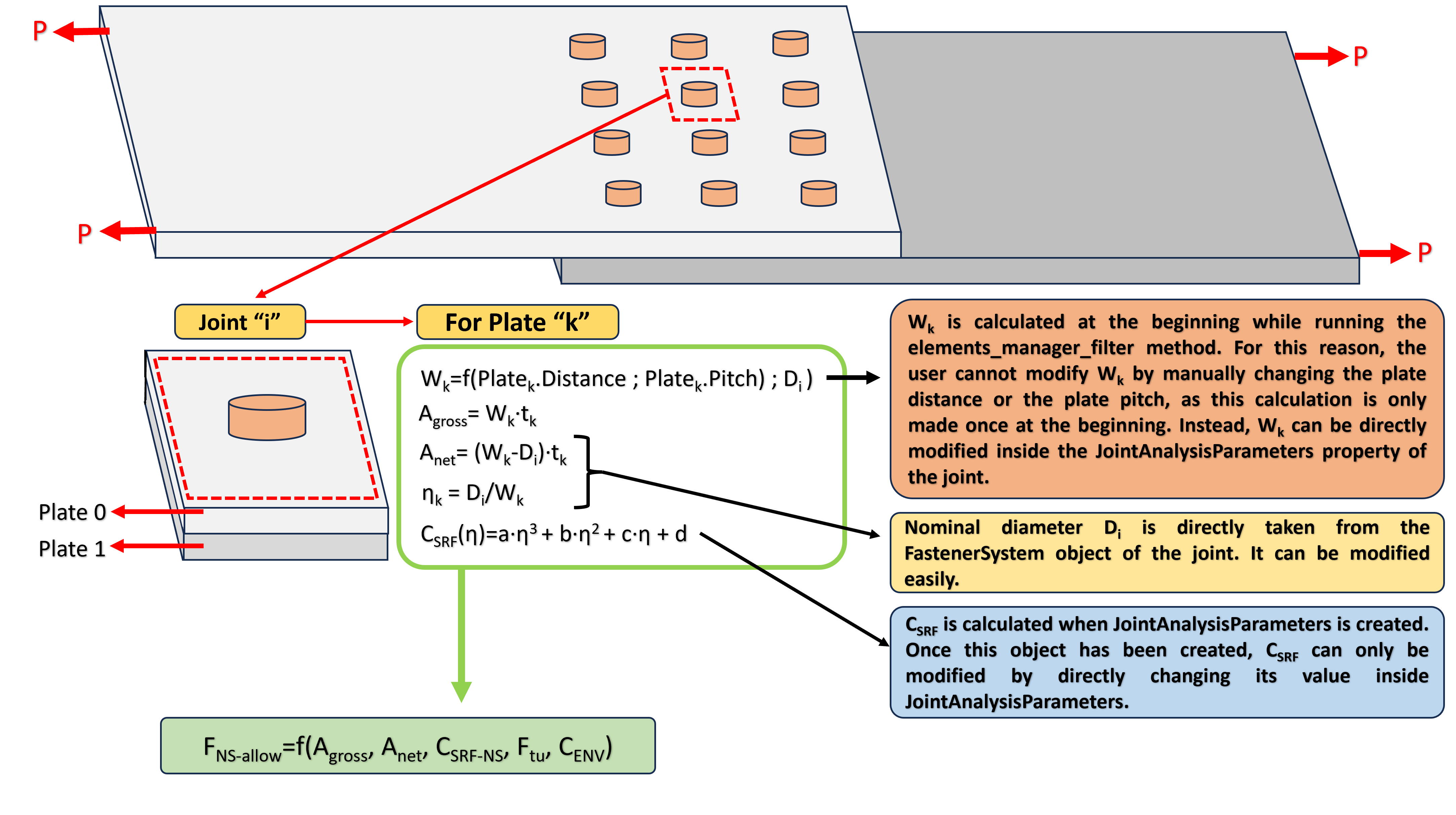
Fig. 6 Different methods to change the value of \(F_{NS-allow}\).#
# Example -> Joints id:(36,54) C_SRF_NS are manually modified by the user

rf = N2PCalculatorRFJoints()
rf.GetFasteners = fasteners
rf.ExportLocation = "path"
rf.elements_manager_filter(mode = "ADVANCED", table_print = "EXCEL")
rf.GetFasteners.JointsList[36].JointAnalysisParameters.Coef_SRF_NetSection_Met = [0.97, 0.97]
rf.GetFasteners.JointsList[54].JointAnalysisParameters.Coef_SRF_NetSection_Met = [1.00, 1.00]
N2PRivetRF #
This class calculates RFs for every CFAST, CBUSH element contained inside each N2PJoint contained inside the N2PGetFasteners input using the available loads introduced through the N2PGetLoadFasteners object.
Bolt Tension (Industrial Method)#
Bolt tension failure occurs when a fastener (e.g., a bolt, rivet, or screw) fails because its applied tensile load exceeds its tensile allowable. The reserve factor associated to this failure mode is calculated using the following expression:
Where the meaning of each element is described as follows:
\(F_{\text{T-allow}}\): fastener allowable tension strength [force], min(Fastener_pin_tensile_allow, Fastener_collar_tensile_allow)
\(UserKDF\): property of the object N2PJointAnalysisParameter (UserKDFBoltTension)
\(C_{\text{prying}}\): property of the object N2PJointAnalysisParameter (CPrying)
\(P\): tension load of the connector for a given load case. For those load cases in which \(P \leq 0\), this RF is printed as 9999.00 at the output as this failure mode cannot take place
Warning
\(F_{\text{T-allow}}\) ->> min(Fastener_pin_tensile_allow, Fastener_collar_tensile_allow) properties of FastenerSystem object.
Note
\(RF_{\text{bolt-tension}}\) is calculated for every single 1D FEM element which constitutes the N2PBolt of a N2PJoint object. This is done for every kind of joint (2,3,4… n plates) and this feature cannot be modified by the user.
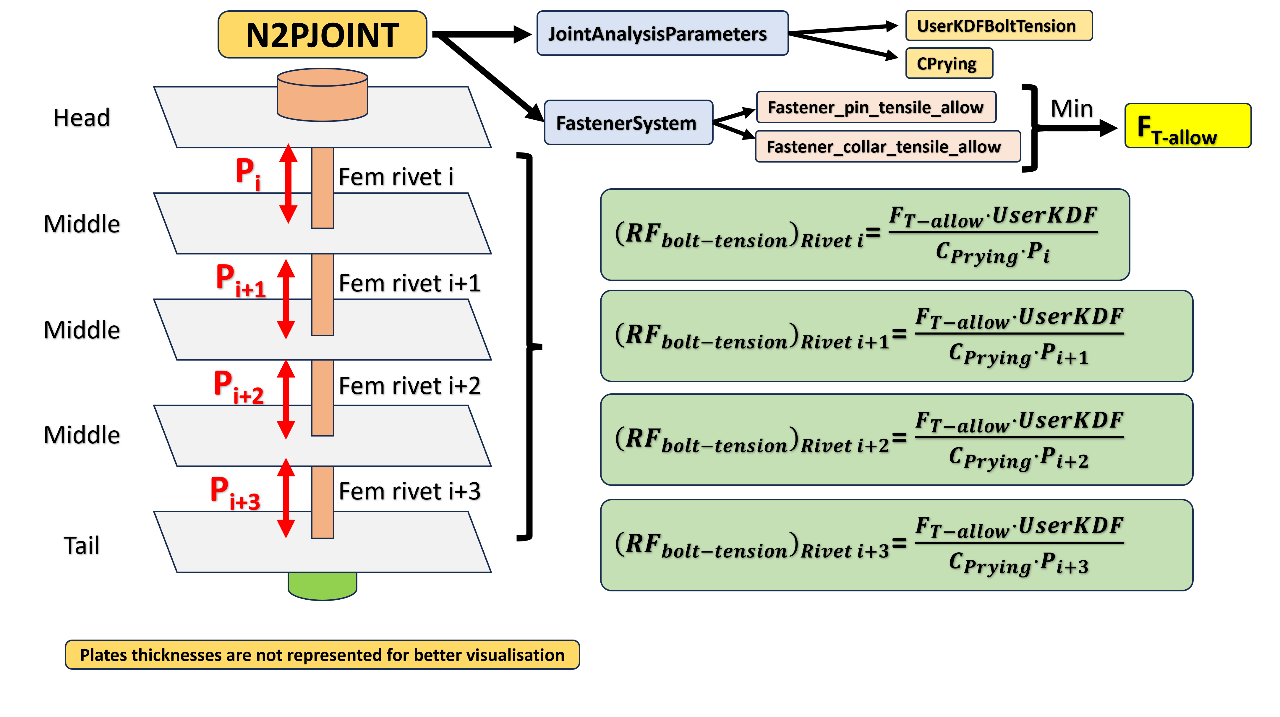
Fig. 7 RF bolt tension failure mode calculation scheme visual example.#
Bolt Shear (Industrial Method)#
Bolt shear failure occurs when a fastener (e.g., a bolt, rivet, or screw) fails because its applied shear load exceeds its shear allowable. The reserve factor associated to this failure mode is calculated using the following expression:
Where the meaning of each element is described as follows:
\(F_{\text{S-allow}}\): fastener allowable shear strength [force], which takes into account the plate side (read warning below)
\(UserKDF\): property of the object N2PJointAnalysisParameter (UserKDFBoltShear)
\(F_{\text{Shear}}\): applied shear load [force] for a given load case and a given plate. For those load cases in which \(F_{\text{Shear}}=0\), this RF is printed as 9999.00 at the output as this failure mode cannot take place
Warning
\(F_{\text{S-allow}}\) ->> Fastener_pin_single_SH_allow for “Head” and “Middle” sides and Fastener_collar_single_SH_allow for “Tail” side.
Note
\(RF_{\text{bolt-shear}}\) is calculated for every single 1D FEM element which constitutes the N2PBolt of a N2PJoint object. This is done for every kind of joint (2,3,4… n plates) and this feature cannot be modified by the user.
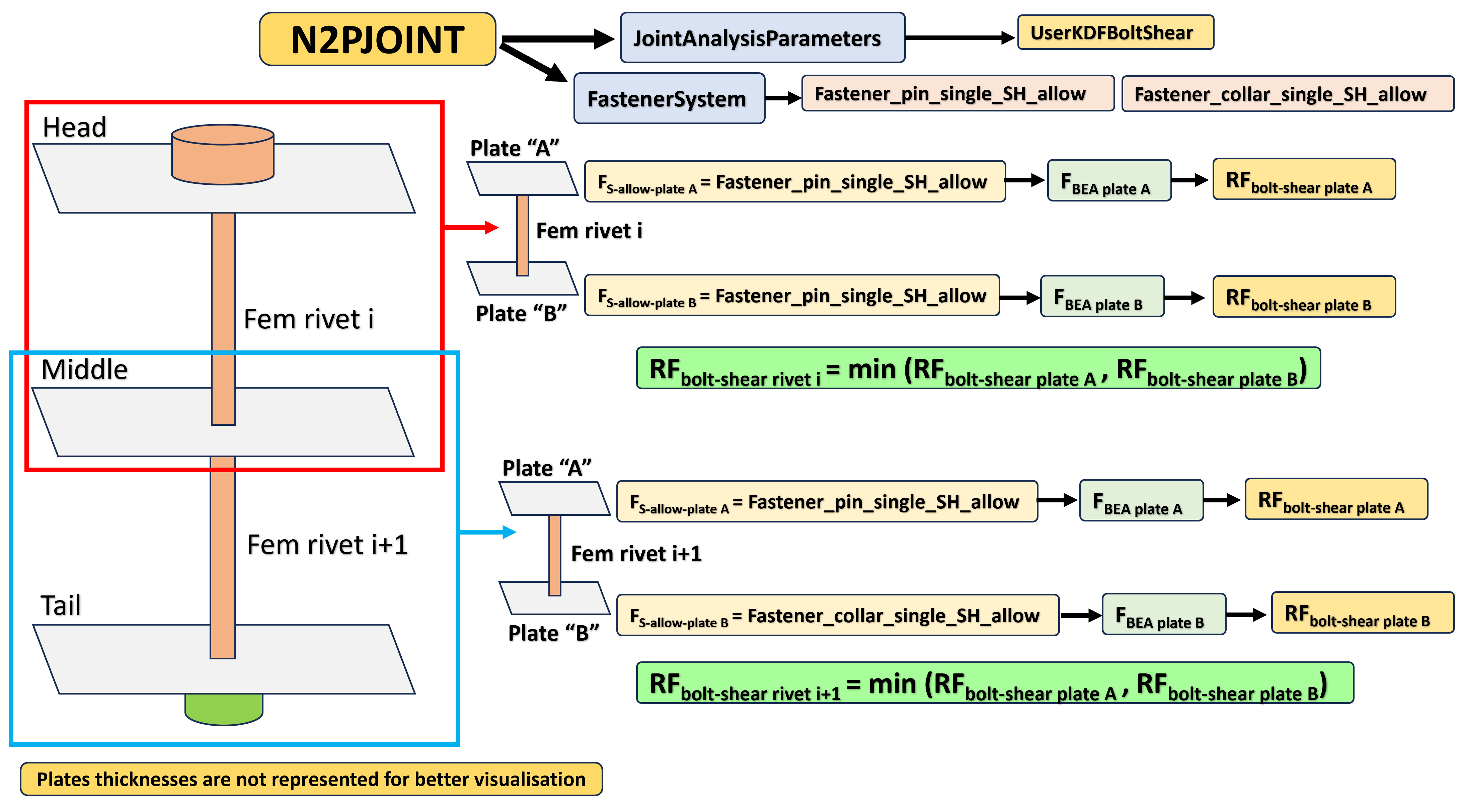
Fig. 8 RF bolt shear failure mode calculation scheme visual example.#
Bolt Combined (Industrial Method)#
Bolt combined failure occurs when a fastener (e.g., a bolt, rivet, or screw) is experiencing shear and tension loads simultaneously and such interaction exceeds a given limit. Once this limit has been exceeded, the bolt fails. Assuming that each 1D FEM element is connected to two different 2D FEM elements (a,b plates), the reserve factor associated to this failure mode is calculated using the following expression:
Where the meaning of each element is described as follows:
Table 11: Bolt combined parameters for composite plates
Parameter |
Description |
User Depending ? |
Input Type |
|---|---|---|---|
\(\alpha\) |
Coefficient alpha for composite combined interaction |
Yes |
Conditional -> N2PJointAnalysisParameters Coef_Alpha_CombinedComp (Default: automatically obtained) |
\(\beta\) |
Coefficient beta for composite combined interaction |
Yes |
Conditional -> N2PJointAnalysisParameters Coef_Beta_CombinedComp (Default: automatically obtained) |
\(R_{T}\) |
\(R_{T}=min \left [\left (RF_{\text{pull-through}} \right); \left (RF_{\text{bolt-tension}} \right) \right]\) |
No |
- |
\(R_{S}\) |
\(R_{S}=RF_{\text{bolt-shear}}\) |
No |
- |
Table 12: Bolt combined parameters for metallic plates
Parameter |
Description |
User Depending ? |
Input Type |
|---|---|---|---|
\(a\) |
Coefficient a for metallic combined interaction |
Yes |
Conditional -> N2PJointAnalysisParameters Coef_A_CombinedMet (Default: automatically obtained) |
\(b\) |
Coefficient b for metallic combined interaction |
Yes |
Conditional -> N2PJointAnalysisParameters Coef_B_CombinedMet (Default: automatically obtained) |
\(R_{T}\) |
\(R_{T}=\left (RF_{bolt-tension} \right)^{-1}\) |
No |
- |
\(R_{S}\) |
\(R_{S}=\left (RF_{bolt-shear} \right)^{-1}\) |
No |
- |
References#
[Ref-1]: A350 XWB Method for Sizing of Bolted Joints Report. Airbus.
[Ref-2]: Airbus Static Method for Metallic Bolted Joints Technical Report. Airbus.
[Ref-3]: Composite Harmonised Bolted Joints Calculation Method Technical Report. Airbus.
[Ref-4]: Composite Course, Bolted and Bonded Joints. Clairis Technologies
[Ref-5]: Mechanical Joint Analysis. Lilium - Aciturri Aerostructures.
[Ref-6]: Internal Interfaces, Composite Panels Attachment. Aciturri Aerostructures.
This guide serves as a comprehensive reference for using the N2PCalculatorRFJoints Module in structural analysis tasks. For further information, refer to the source code comments and examples provided.

All rights reserved. This document is licensed under the terms of the LICENSE of the NaxToPy package.